

TOYOTA L/C SAGINAW STEERING:
A Saginaw steering conversion for these vehicles is a proven advantage simply because they allow you to have better control of your vehicle both on and off the highway. The stock steering is a gearbox at the base of the steering column controls a drag link. A bellcrank is mounted on the front crossmember and uses a push-pull effect for steering. This assembly uses six tie-rod ends, which allow excessive free play and backlash. The saginaw steering will offer you a sound positive means of controlling your vehicle, it can be performed at a reasonable cost. Additional advantages include exhaust clearance, engine positioning, and custom steering columns. These kits are designed for the FJ40 Land Cruiser vehicles only.
Before you consider this conversion, we recommend that you thoroughly read and understand the complete installation procedure. Do not take shortcuts on steering installations. We recommend that these conversions be installed by a qualified technician. The control of your vehicle depends on your steering performance. Failure of your steering system can result in severe damage and possible injury.

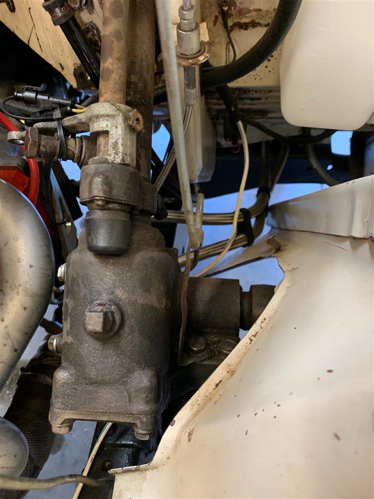
SAGINAW STEERING KITS: All of the Toyota FJ40 Land Cruisers had basically the same stock steering configuration. It is simply a gear box at the base of the steering column which controls a drag link towards the front of the vehicle. A bellcrank is mounted on the front crossmember and uses a push-pull affect for steering. This assembly uses six tie rod ends which, in many cases, allows excessive free play and backlash.
The Saginaw steering system requires the elimination of the stock gear box and bellcrank. The new steering box is mounted on the inside of the left front frame rail, just behind the bumper. Although this sounds simple, there are several things that must be considered before the installation can be completed. Such things include:
Power or manual steering Steering column type Steering box location Motor mount clearance on steering shaft Tie rod size & length Winch clearance
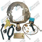
We offer four (4) steering conversion kits. These kits are either power or manual steering conversions, and either a Borgeson/Flaming River or Spicer yoke design. None of these kits supply the steering box (manual or power), or steering pump and hoses (power applications).
Both the manual and power steering conversions can be performed with the original 6 cylinder engine or a new Chevy V8. There may be slight modifications required to the driver’s side engine mount to provide proper clearance for the steering driveshaft. On 3 speed Land Cruisers equipped with a column shifted transmission, you will need to change your 3 speed linkage to a floor shifter. The power steering conversions retaining the stock 6 cylinder will also require a custom power steering pump mounting bracket, Part No 716842. To help identify the kit necessary for your conversion, please consider the following information.
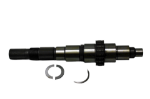
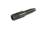
POWER & MANUAL STEERING BOX SELECTION: The Saginaw steering box gets mounted just behind the front bumper. This requires a clearance hole to be cut in the stock support located under the radiator for the steering shaft. Since the Saginaw steering shaft has a short stickout from the box, a spud shaft (or extension shaft) must be added to the steering box to extend the steering shaft into the engine compartment. There are three different spline sizes on the different Saginaw power and manual boxes. Both Power and Manual boxes have two spline sizes that mate to our spud shaft. Both Power & Manual boxes can be found in the 1960s & early 1970 GM cars, or Jeep vehicles 1972 & newer. The manual steering box must have a shaft stickout length of approximately 3” long, and the spline on the shaft approximately 1” long. When using power steering, we recommend obtaining the pump and hoses off of the same vehicle. We now offer boxes & pumps listed at the end of the Steering section.
Both Power and Manual boxes have two spline sizes that mate to our spud shaft. Our manual steering kits are supplied with a .730” dia. 30 spline spud shaft. If your steering box has .730” dia. 36 spline, Part No. 716834-36 can be substituted. On power steering kits, we supply the most common spud shaft which is a .800” dia. 36 spline. On some of the newer Saginaw boxes, we have found them to have a .730” dia. 30 spline. Part No. 716834-30 can be substituted.
716834-30 - Spud shaft .730” dia. 30sp. female x 1” Double D Male (power & manual boxes)
716834-36 - Spud shaft .730” dia. 36sp. female x 1” Double D Male (manual boxes only)
716835 - Spud shaft .800” dia. 36sp. female** (power boxes) **716835 will be switching to 1” Double D Male in 2014.
BORGESON / FLAMING RIVER KITS: These kits are the newest and most recommended style that we manufacture. The steering shaft assembly connects directly to our steering spud shaft. This collapsible slip steering shaft extends to the firewall and can be adjusted to any length. The 3/4” DD connection (round shaft having 2 flat surfaces) couples easily to any of the yokes supplied in the kit or listed under the Custom Steering Column subheading. These kits require welding on the steering box mounting plate, frame enclosures, and firewall mounting plate.
716807 - Land Cruiser conversion kit, Manual Saginaw box0
716808 - Land Cruiser conversion kit, Power Saginaw box
716808A - Land Cruiser conversion kit, Power Saginaw box (minus spud shaft and colum yoke)
(These kits do not include boxes or pumps)
STEERING COLUMNS: The stock steering column is the easiest option when installing the Saginaw steering. If you are planning to use a custom steering column, some fabrication will be necessary for mounting.
The stock steering column protrudes through the firewall and into the engine compartment. There are two basic steering column configurations. Vehicles prior to September 1972 were one style, and vehicles after this date were another. The biggest difference between these steering columns is the anchoring of the column to the firewall.
Steering Columns September 1972 & Earlier: These earlier models are equipped with a steering mechanism that clamps directly onto the Toyota gear box. The firewall mounting plate bolts through the firewall with either four bolts or six bolts, depending on the actual year. In order to install the Saginaw steering, you must install a Universal yoke on the end of the steering column. We suggest that you follow this step-by-step procedure:
Step 1: Using a hacksaw or torch, remove the steering column and shaft from the original steering box. Make the cut as close as possible to the steering box so that an adequate amount of the steering column shaft will be available.
Step 2: Remove the original Land Cruiser gear box, Pitman arm, drag link, bellcrank, stock stabilizer, and front tie rod.
Step 3: Remove the turn signal switch.
Step 4: Remove the firewall dust boot and retainer plate.
Step 5: In order to relocate the steering column after it has been removed, we suggest that you wrap a piece of masking tape around the column as a guide to the original location. This will provide a means of relocating the column back to the original location.
Step 6: Using the column mounting plate provided, you can now slip the plate onto the column, making sure that it can be adjusted to the proper angle for reassembly onto the firewall.
Step 7: Slip the column and the plate back into the vehicle to the original location. Tack weld the column and column mounting plate into position. Using the nut plate on the engine compartment side of the firewall, you can now locate the hole locations required for bolting the mounting plate into position.
Step 8: Once again, remove the column and finish welding the mounting plate to the column tube. Drill the mounting holes out to a larger size for use with the original bolts.
Step 9: Determine the length of the column tube and the 3/4" column shaft and cut to the necessary length. We recommend that the column protrude 2" from the face of the firewall, and the shaft protrude 2" beyond the end of the tube. On various installations, this length may vary to allow for engine mount and steering driveshaft clearances.
Step 10: Install the brass/teflon bushing provided with the steering kit into the bottom of the steering column tube. Make sure the clearance between the bushing and the shaft is sufficient. You may need to sand the column to obtain the proper fit. In our experience with the stock Land Cruiser column shaft, we found the size to be approximately .007" larger than the 3/4" yoke.
Step 11: In order to retain the brass bushing in the end of the column, you will need to weld a flat washer or use a set collar on the steering column shaft. This washer or set collar must be flush with the bushing. If a washer is used, weld it 360 degrees around the shaft.
Step 12: On the Flaming River kit, a 3/4" Double "D" yoke has been provided for this application. The 3/4" column shaft will need to be modified to fit the Double "D" yoke. With a disk grinder, grind 2 flats about .100" deep on each side of your stock column shaft. There are two set screws in the new Universal yoke assembly. Mark the location on the steering shaft where these two set screws are located. Remove the Universal yoke and spot drill two recesses for the set screw installation, approximately 3/16" deep. Reinstall the universal yoke and set both of the two set screws and lock nuts. Loctite should be used on both set screw installations.
Step 13: Reinstall the column back into the vehicle and bolt the mounting plate into position.
Steering Columns October 1972 & 1979: These later models are equipped with a steering column that uses a 4-bolt mounting plate to the firewall, and a special coupler for connecting to the stock steering box. Vehicles equipped with this particular model will be able to leave the column in the vehicle while making the necessary modifications. We suggest that you follow this step-by-step procedure as listed below.
Step 1: Using a hacksaw, remove the special coupler from the end of the shaft. Make the cut as close as possible to the coupler.
Step 2: Remove the 4 nuts that hold the column mounting plate in position and install the new Advance Adapters bearing assembly. New bolts have been provided for use with our new support bearing.
Step 3: Check to make sure that the bearing and shaft have sufficient clearance for a smooth operation. You may need to clean and sand the steering column shaft to obtain the proper fit. At this point, you should lock the bearing onto the shaft using the set screw provided.
Step 4: Determine the length of the steering column shaft that is best suited for your engine location. Cut the shaft to the appropriate length and, once again, debur and clean for a slip fit of the 3/4" Universal yoke.
Step 5: On the Flaming River kit, a 3/4" Double "D" yoke has been provided for this application. The 3/4" column shaft will need to be modified to fit the Double "D" yoke. With a disk grinder, grind 2 flats about .100" deep on each side of your stock column shaft. There are two set screws in the new Universal yoke assembly. Mark the location on the steering shaft where these two set screws are located. Remove the Universal yoke and spot drill two recesses for the set screw installation, approximately 3/16" deep. Reinstall the universal yoke and set both of the two set screws and lock nuts. Loctite should be used on both set screw installations.
CUSTOM STEERING COLUMNS: Custom columns offer several distinct advantages. The advantages include locks, tilts, flashers, and custom vehicle appearance. When upgrading to the Saginaw steering, it’s easiest to retain the stock steering column; however, we now offer a clean and easy way of mounting a GM column to your floorboard. This mounting bracket provides a clamping support for a 2-1/4” new steering column.
716866 - 2-1/4” steering column support
Flaming River / Borgeson: Universal joints are available to match nearly every style steering column available. The special spline size on some of the custom columns will require a different U-joint than supplied in our kits. We offer a selection of the various sizes. The new universal joint is supplied with a mating connection that will fit the new 3/4” DD steering shaft. If a custom column is being used and you have already purchased the stock Toyota 3/4” diameter column yoke, you will then need to exchange your universal joint for the one that will be required on your installation. The special yoke assemblies to connect a custom steering column to our Saginaw steering components are as follows.
716848 - 1” 48 spline Universal yoke (GM columns)
716849 - 1” DD Universal yoke (GM and Ford)
716850 - 3/4” x 36 spline Universal yoke (GM and Ford) (The dimensions represent the column side of these yokes only. The opposite side of these yokes is a 3/4” DD)
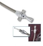
STEERING DRIVESHAFT: The control shaft between the end of the column and the steering box spud shaft is defined as the steering driveshaft.
Flaming River / Borgeson: With each kit, we have provided a 3/4” DD shaft that has a length of 36”, and a special U-joint is included to fit the bottom of the shaft. The shaft will have to be shortened to the necessary length for your installation. The new shaft assembly has a 3/4” DD end that will need to fit into the steering column universal joint. Use the same procedure to spot drill both of the set screws, and Loctite the connections with the two lock nuts.
This steering driveshaft is a collapsible assembly. The lower portion of this driveshaft assembly is supplied with a 36 tooth fine spline connector or a 1” Double D yoke that will fit directly onto the steering box or AA spud shaft. Always use Loctite on the double set screws and lock nuts for all universal yoke connections.
ROUTING THE STEERING DRIVESHAFT: Routing the steering driveshaft may seem simple, but care should be taken as to the actual routing. On some Land Cruiser installations, it may be necessary to go directly through the motor mount; however, most will have the steering shaft well above the engine mounts. Routes may be adjusted by changing the angle of the steering box slightly, or by extending the universal yoke from the column bushing with a spacer. Before any final route is decided, be sure to allow for suspension travel and engine movement. Be sure that your angles do not exceed a total of 30 degrees, or 15 degrees per universal. If more severe angles are used, the universal yokes will bind, causing major steering difficulties. On some conversions, a third universal yoke might be considered along with a bearing pillow block.
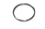
FRONT CROSSMEMBER: When installing the Saginaw conversion, the front crossmember will require an access hole that is roughly 3” in diameter to provide clearance for the steering spud shaft clamp. This access hole allows the steering spud shaft to extend through and into the engine compartment. In most cases, the front crossmember must be reinforced on both the top & bottom because of the diameter of the access hole.
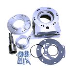
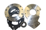
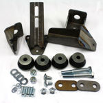
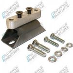
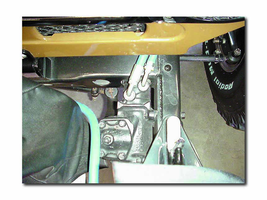
STEERING BOX LOCATION: The power steering box will require every bit of space between the bumper and front crossmember. The actual positioning of the steering box should be accomplished by bolting the box to the plate provided, and then temporarily clamping the plate and box to the inner frame rail until an ideal position is achieved. Make sure this position allows the steering spud shaft to extend through the front crossmember and into the engine compartment. Once in position, the plate must be completely welded to the frame. Since this plate encounters extreme forces from the steering system, the welding of this plate should be done by a certified welder.
The steering box mounting plate must have a solid surface for welding and positioning. We have provided a extra 3/16” thick steel frame enclosures to box the passenger side of your frame rail. The extra plate is simply supplied for boxing of the passenger side frame rail. On vehicles equipped with winches, it may be necessary to offset the winch bumper to allow for the steering box clearance.
Before the box can be mounted to the frame rails, you will need to torch or drill two large clearance holes into the front crossmember. These holes will provide clearance for the steering box spud shaft to go beneath the radiator and enter into the engine compartment area. The hole on the front side should be at least 3” in diameter, while the backside hole can be 1-1/2” in diameter. If you have moved your radiator from the original location, you may require radiator modifications. The upper bumper gusset may need to be sectioned for the mounting of the steering box plate.
When using the mounting plate and frame enclosures (716839), you will be required to have these components welded onto your frame rails. These welds should be made only by a qualified welder. Do not short change your installation with a poor quality weld of these mounting plates to your frame rail. The plates should be welded along the complete perimeter.
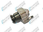
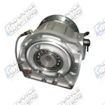
SAGINAW STEERING BOXES: Power and Manual steering gear boxes are very similar. We have already illustrated what the two boxes should look like. Normal applications were on GM cars, but a few other vehicles also used the same boxes. The steering box must be able to mount on the inside frame rail of your vehicle, with the input shaft extending horizontally toward the firewall. This input shaft is normally not long enough to extend fully into the engine compartment to couple with the steering driveshaft. This is why we offer steering spud shafts to extend these steering box input shafts.
Power: On power steering boxes, you will be required to use four bolts when using our mounting plate, 716839. The 4 bolts must be installed from the bracket side into the steering box. Some of the newer Chevy boxes come only with a 3 bolt mounting flange. This is similar to the manual steering boxes. 716839 will still work on these boxes. DO NOT drill out the threads in the power steering box assembly.
Manual: The manual steering box mounts to the mounting plate with only three bolts. These bolts come through the mounting plate and fasten to the steering box. We use the same mounting plate, 716839, as we do for the power box.
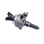
Saginaw Steering Box: We offer a custom rebuilt heavy-duty power steering box. This box offers you a variable 16-13 to 1 ratio which produces better steering characteristics for both on and off road. This box offers a 3-3/8” turn lock-to-lock ratio, a heavier torsion shaft for a better feel of the road, a 30 spline input, and uses the o-ring style hose fittings. This box can be ordered under P/N 716882. TIE RODS: Each of our kits include the necessary short tie rod for your conversion. This tie rod has a special left hand metric thread and one right hand American thread. The tie rod connects to the Saginaw pitman arm and then to the stock Land Cruiser tie rod end located on the passenger side. Care should be taken for the proper fit of the tie rod end’s taper and threads when installing into the Pitman arm. In some cases, it may be necessary to use two or three washers on the top side of the Pitman Arm so that the threads on the tie rod end will secure the proper taper fit. All tie rod ends must be secured with a castle nut and cotter pin. All tie rod-to-tie rod end connections must have a tie rod clamp installed with a bolt, lock washer, and nut. We DO NOT find it acceptable to cut and weld the tie rods.
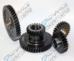
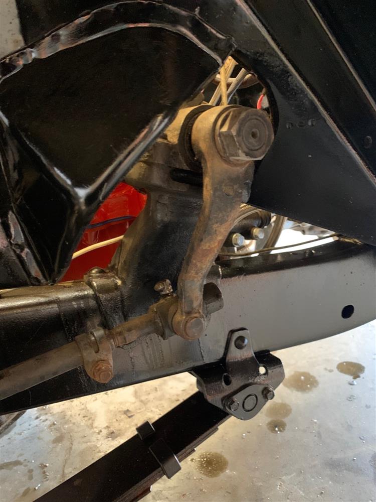
PITMAN ARMS: The steering box Pitman arms vary from power to manual, and are not interchangeable. The Pitman arm supplied in each kit is for use on vehicles that are not equipped with a suspension lift. If your vehicle requires a dropped Pitman Arm, then we suggest that you contact a suspension lift company. We DO NOT find it acceptable to cut or bend our Pitman arms.
POWER STEERING PUMPS: There are only a few pumps available and most are interchangeable. We recommend the purchase of the power steering pump and steering box as a pair if possible. For proper installation, special hoses will probably have to be made. The hardware for mounting the pump to the engine can be standard parts from Chevy & Ford engines. Stock 6 cylinder applications require a special pump mounting bracket. We offer this mounting bracket under P/N 716842 which fits 1975-81 vehicles. The power steering pully for the Saginaw pump can be purchased from Man-A-Free.
TURNING ANGLE ADJUSTMENT: To avoid damage to the outer axle U-joints, it is advisable that you check the turning angle. To adjust the turning angle stops, loosen the lock nut and turn the adjustment screw. The adjusting screw is located on the axle tube near the knuckle housing. For further detailed information, refer to your vehicle service manual.
CASTER ADJUSTMENT: The purpose of the caster adjustment is to provide steering stability, which will keep the front wheels in a straight ahead position. It also assists in straightening the wheels after making a turn. If the angle of the caster is found to be incorrect, correct it to the specifications given in your service manual. The correct angle is obtained by installing caster shims between the axle pad and the springs. If the camber and the toe-in are correct and it is known that the axle is not twisted, a check may be made by testing the vehicle on the road. Before road testing, make sure that the tires are properly inflated at the same pressure. If the vehicle turns easy to either side, but is hard to straighten out, insufficient caster for ease of handling is indicated. If correction is necessary, it can be accomplished by changing the shims between the spring and axle pads.
TOE-IN ADJUSTMENT: Lift the front of the vehicle to raise the front tires off of the ground. Turn the wheels to the straight ahead position. Using a pencil or chalk, scribe a line in the center of each tire tread. The mark should circle the entire diameter of the tire. Measure the distance between the scribe lines at the front and rear of the wheels, using care that both measurements are made at an equal distance from the floor level. The distance between the lines should be greater at the rear then at the front by 3/64" to 3/32”. To adjust, loosen the clamp bolts and turn the long tie rod with a small pipe wrench. The tie rod is threaded with right hand and left hand threads to provide equal adjustment at both wheels. Do not overlook the retightening of the two clamp bolts. It is a common practice to measure between the wheel rims. This is satisfactory providing the wheels run true. By scribing a line on the tire thread, a measurement is taken between the road contact points reducing error caused by wheel rim run out.
It is recommended to have the alignment done by a qualified technician.
STEERING COMPONENTS: Although we manufacture and sell complete kits for Saginaw steering conversions, we do offer the individual components.
716811 - Stock Land Cruiser column bushing (up to 1972)
716812 - Tie rod clamp
716814 - Spud shaft clamp
716816 - Manual pitman arm
716817 - Power pitman arm
716821 - Right hand thread tie rod end
716822 - Land Cruiser column mounting plate
716831 - Land Cruiser tie rod 25-1/2”
716833 - Land Cruiser column bushing (1972 &1979)
716834-30 - Spud shaft .730” dia. x 30T (1” male DD)(manual & power)
716834-36 - Spud shaft .730” dia. x 36T (1” male DD)(manual)
716835 - Spud shaft .800” dia. x 36T (1” male DD late 2014)(power)
716839 - Power and Manual steering box mounting plate (with passenger side frame enclosure)
716841 - Universal Joint 1” DD x 1” DD
716842 - Land Cruiser 6 cylinder power steering pump bracket
716845 - Universal Joint 1” DD x 3/4” - 36 Spline
716848 - Universal Joint 3/4” DD x 1”-48 GM
716849 - Universal Joint 3/4” DD x 1”DD
716851 - Land Cruiser column yoke with a 3/4” DD
716860 - Steering shaft support bushing (for a pillow block assembly.)
716862 - Collapsible steering shaft and yoke assembly
716863 - Collapsible steering shaft
716881 - Saginaw power steering box After 1980 with o-ring fittings .800 dia., 36 spline input shaft
716882 - Saginaw power steering box After 1980 with o-ring fittings .730 dia., 30 spline input shaft
")

