

Toyota 4WD trucks have been one of the more popular vehicles for the past several years. This is due in part to their performance, reliability, and excellent engineering.
Back in 1981, we first introduced a kit to install a Buick V6 with a TH350 transmission into these vehicles thus enhancing performance. Over the years, we have consistently updated and created new kits to meet the needs of the Toyota owner. We feel that these kits, when installed properly, will provide you with the same reliability and service that your stock vehicle once had.
There have been several variations of the Toyota pickup over the years. Different transmissions, transfer cases, and different body styles have been used. These changes created a variety of different adapters necessary when converting these vehicles. As you read through this manual, it is important that you look over the pages that pertain to your vehicle specifications. Proper identification of you stock drivetrain components is required. The use of this manual will aid in the stock drivetrain identification.
TOOLS REQUIRED:
Toyota pickups are put together with all metric fasteners. If you do not have a good selection of metric and standard wrenches, then we would suggest that you purchase the appropriate wrenches before you start your conversion. Along with these tools, it is advised that you have an engine hoist and a torque wrench to complete the conversion properly. Some conversions do require some welding or cutting for mounting of the engine. Please refer to your specific vehicle application listed in this manual for further information concerning modifications. For electrical wiring diagrams and Toyota torque specifications, you will need a Toyota 4WD service manual.
ENGINE SELECTION:
The first step is to define the use of the vehicle and then select a motor which best fits those needs. We manufacture motor mounts, headers, and adapters for most Chevy V6 and V8 engines, along with the Buick V6 & Ford V8 engines. Within this range of motors every practical need can be met. The engine size can create clearance problems in regard to the radiator, suspension, and firewall. These are an important factors when determining which engine to use.
SMALL BLOCK CHEVY V8:
* Addition note to the small block Chevy V8 section * Caution should be used if you plan on using a newer Chevy V8 or 4.3 V6. We have seen aluminum oil pans on most 1997 & later model blocks. This could cause problems with some of our bellhousing conversions since these oil pans also provided mounting holes for the stock bellhousing and because our conversion bellhousings do not offer these mounting options. Vehicles using these new blocks should consider retaining the stock transmission that was originally coupled to this engine. We offer a full line of transfer case adapters to couple these newer transmissions to your transfer case. This aluminum pan could also cause problems on vehicles 1986 & up without a suspension lift.
We do not recommend the installation of Generation III Vortec engines for Toyota Trucks. The narrowest exhaust we could find is 25”, and the Toyota frame rail is 23”. The height and width of this engine is too large for a good, clean fit.
ENGINE INFORMATION:
Toyota Truck Engine Swap Info:
Toyota Truck Transfer Case Info:
TOYOTA CONVERSIONS
“STEP BY STEP” GUIDE
The following step-by-step procedures are to be used as a guide only in performing your Toyota 4WD engine and transmission conversion. There are several variations and exceptions to these procedures. We recommend that you refer to your Toyota Service Manual for specific electrical, torque, and gasket specifications. If you are in doubt on any of the information listed on the following pages, please contact our technical department. In addition to this manual, you will have individual instruction sheets on the engine motor mounts and transfer case-to-transmission adapter kits. We recommend that you carefully read both sets of instructions while performing your conversion.
REMOVING THE ENGINE & TRANSMISSION:
1. Remove the front and rear drivelines.
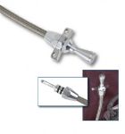
2. Disconnect the speedometer cable from transfer case.
3. Disconnect the throttle linkage from the engine.
4. Drain and remove the radiator assembly.
5. Disconnect the alternator and battery.
6. Disconnect the temperature and oil pressure sending units. Identify these wires for future use.
7. Remove the hood and complete exhaust system.
8. Disconnect the clutch slave cylinder and hydraulic line.
9. Remove the transmission shift lever.
10. Remove the transfer case shift lever.
11. On the stock coil, you will find a yellow wire that connects to the positive terminal. Disconnect this wire and mark it for future use with the new engine. Remove the coil and igniter.
12. Disconnect the power steering pump hoses from the engine.
13. Disconnect the air conditioning compressor lines.
14. Check the engine and transmission for any items that have not been disconnected.
15. Attach an engine hoist to the engine assembly.
16. Place a small jack or transmission floor jack directly beneath the transfer case and transmission. With the jack in position, you can now remove the four transfer case mounting bolts and disconnect the transfer case crossmember.
17. Disconnect the bellhousing from the back of the block, as the engine and transmission assembly must be removed separately.
18. Remove the engine mount nuts that hold the engine mounting rubber to the engine perch.
19. Remove the engine from the engine compartment.
NOTE: When removing engine, make sure the transmission and transfer case are properly supported.
20. Remove the transmission and transfer case.
ENGINE PREPARATION:
1. Depending on which engine is being used, it is best to install all of the brackets, pulleys, and accessories prior to assembly into the vehicle. This will be the installer's option if he desires to assemble these parts after the engine has been positioned into the vehicle.
2. The temperature sending unit from the original Toyota engine can now be installed into the new engine block.
3. The oil pressure switch from the original engine must be used with the new engine if the original dash gauge is going to be retained.
4. The power steering pump, air conditioning bracket, and alternator bracket can now be fastened to the engine - depending on the vehicle requirements. Refer to the Engine Conversion section for the recommended bracketry and alternate solutions.
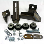
5. The engine mounts can now be bolted onto the engine, depending on which engine and which type of suspension your vehicle will be equipped with. Refer to the motor mount instruction sheets for these requirements.
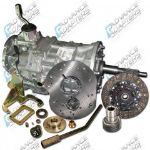
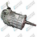
INSTALLING A MANUAL 5 SPEED TRANSMISSION:
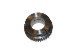
1. With your new engine prepared, you must first bolt the correct flywheel onto the engine crank. Make sure the proper torque specifications are used.
2. Install new pilot bearing into the engine crank shaft.
3. The Centerforce pressure plate and clutch disc can now be bolted to the flywheel. Be sure to align the clutch disc and pilot input shaft before securing the pressure plate.
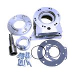
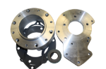
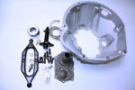
4. The 5 speed bellhousing will bolt to the transmission from the inside of the bellhousing. Use the original bolts with the new bellhousing. Install the release lever & release lever ball pivot.
5. Mount the slave cylinder onto the bellhousing and make sure the alignment of the push rod & release lever are properly located.
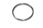
6. Install release bearing P/N N1430 over the Toyota transmission bearing retainer. On the inside of the release bearing, you will find a small groove that must be packed with grease. This will provide lubrication between the bearing and the bearing collar.
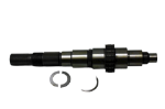
7. With the bellhousing, transmission, and throw out bearing assembled, you can now bolt the bellhousing to the new engine. Make sure that the dowel pins align the engine block and the bellhousing. DO NOT FORCE the assembly together. The input shaft of the transmission must fit smoothly into the new pilot bearing and engine crank. The tip of the input shaft must engage the pilot bearing with a minimum of 1/2" contact. With the bellhousing in position, the release bearing should have approximately 1/16" clearance between the clutch fingers. You may need to adjust the length of the slave cylinder push rod in order to obtain the proper clearance between the release bearing and clutch fingers. A return spring on the clutch fork is recommended whenever possible. The original Toyota slave cylinder fitting will screw directly into the Land Cruiser slave cylinder assembly. After securing all of the fittings, you will need to bleed the slave cylinder. Refer to your Toyota Service Manual for bleeding instructions.
ENGINE & TRANSMISSION INSTALLATION:
Most conversions will require the drivetrain to be installed into the vehicle in two parts. The transmission & transfer case should be set back up on the crossmember and into the vehicle. By using an engine hoist, lower the new engine into your engine compartment. Before securing the motor mounts or crossmember, bolt the transmission to the engine.
1. Check to make sure that all components have the necessary clearance. On vehicles equipped with the I.F.S. suspension, you will be required to use a suspension lift in order to have sufficient oil pan clearance. (Refer to the subheadings “Body & Suspension Lift” under the Engine Conversion section for more information).
2. Position the engine mounts for either welding or bolting into position.
3. Make the necessary modifications for the transfer case support. Chevy V8 to 5 speed installations will require the crossmember mounting holes to be elongated approximately 3/8".
4. On V8 conversions using HEI distributors, you may be required to modify the firewall for clearance of the distributor cap.
5. Install front and rear drivelines.
6. Install the speedometer cable & transfer case indicator switch.
7. Install the throttle cable linkage. This may vary depending on which type of manifold and carburetor that is being used.
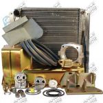
8. The radiator can now be positioned into the original mounting brackets. The radiator can either be the A/A 4-core copper/brass radiator (vehicles 1985 & up) or our Rad-A-Cool aluminum single core radiator (for 1979-95 vehicles). These radiators have the trans coolers built into the radiator system. We recommend a 1-1/2" hose connection for both the inlet and outlet, and we have found it best to use the universal flex hoses for most installations.
9. Connect the starter wires, alternator wires, and battery terminal. Make sure that your engine is equipped with a ground wire.
10. The vacuum connections for both the automatic transmission and brake booster must be reinstalled onto the new engine. Available at most part stores are multi-fitted vacuum hose connectors. These will provide for several vacuum hose connections onto your new manifold.
11. Install your new exhaust manifolds. The manifolds can be either the stock cast iron type, or our "SlickFit” headers.
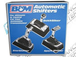
12. The transmission and transfer case shift levers can now be reinstalled. If an automatic transmission is being used, you will need to purchase a floor console type shifter from various suppliers. Both Hurst and B & M offer excellent automatic transmission shifter kits.
13. You will not be able to use the original 4 cylinder coil and igniter, since they will not be compatible with your new engine. The original yellow wire that was attached to the stock coil will be your main feed line to the new ignition system. Depending on your distributor selection will determine your need for an external resistor. On Mallory dual point installations, an external resistor will be required.
AUTOMATIC TRANSMISSIONS TO ENGINE ASSEMBLY:
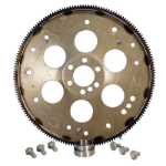
1. Install the correct flywheel (flexplate) onto the engine crank using the special flywheel bolts torqued to the proper specification.
2. Install the torque converter onto the transmission pump. Make sure both sets of torque converter female splines are engaged into the input shaft male splines. CAUTION: There are two sets of splines and it is very critical that the convertor seats into both sets.
3. The transmission can now be assembled to the engine block. Make sure the dowel pins align the transmission case and engine block.
4. With the transmission and engine now assembled, you must install the bolts between the torque converter and flywheel. The torque converter should require approximately 1/8" movement from the seated position outward to meet the flywheel. If this movement outward is not obtained and the converter is jamming the flywheel, you will probably find that the convertor was not installed properly.
5. Install the stock inspection cover.
6. The small flanges on each side of the transmission will need to be trimmed for the exhaust system clearances. This trimming will also need to be done on both the inspection cover and transmission case.


