
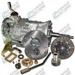
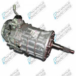
Land Rover Series Transfer Case
We offer 2 different adapters that couple the Land Rover “Series” transfer case to several different transmissions. The adapters are all the same in that they adapt the “Series” transfer case to a circular transmission bolt pattern. This circular pattern is what Jeep used beginning from 1980 to newer Jeep drivetrains. Being that we offer a full line of GM, Ford & Dodge transmission options for Jeeps, using the Jeep adapter with the new Land Rover adapter offers limitless choices. There are three Land Rover adapters because of the different transmission output spline options. The kits are as follows:
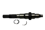
50-9000 - 23 spline kit fits most stock Jeep transmissions as well as and transmissions we offer Jeep transfer case adapters for. For transmissions like the Ford T18 & NP435, you will need to purchase a Jeep adapter also.
50-9001 - Fits only the Dodge NV4500 transmission with a 29 spline output shaft.
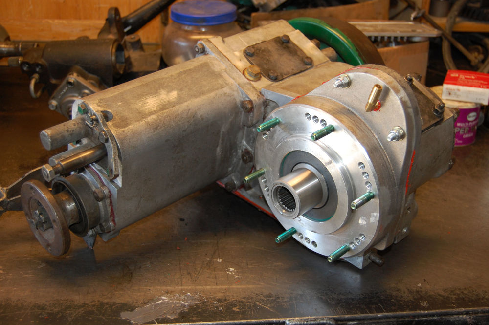
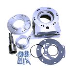
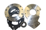
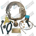
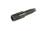
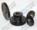
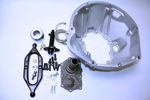
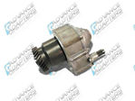
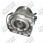
These adapters have been designed for the series I,II,IIA,IIB and III transfer cases, including both the rare 1 ton and the aftermarket overdriven versions. Essentially, this adapter is installed on the front side of the “series” transfer case. This adapter is used in conjunction with one of our Dana 300 adapters or a stock tailhousing. The adapter is constructed of 356-T6 heat-treated aluminum alloy. The spud shaft is a precision machined shaft made of 8620 material. The spud shaft is supported by two large ball bearings and has an external seal. By manufacturing the adapter this way the shaft is supported very well. The adapter has provisions to cover the relocated idler pin in the overdrive, aftermarket version. The stock drive gear train is retained and reused in the transfer case. The front side if the adapter is modeled after the Atlas and Dana 300 transfer case. The mounting surface is a circular six with multiple rotation options. This allows the installer to fine tune the installation of the replacement transmission and engine combination. The adapter is 1.750” thick.
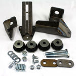
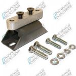
Chassis modifications:
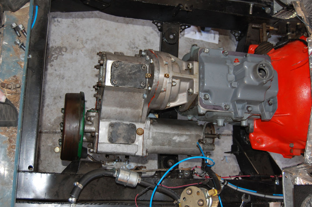
The battery tray structure will have to be removed to allow the fitment of a “V” type engine. The original motor mounts need to be cut off the frame. The front cross member will require a notch or scallop made for front driveshaft clearance, similar to the military LWB. On some series I,II,IIA, it is advisable to remove the web on the front crossmember. The web is on the driver’s side (LHD). This provides clearance for the exhaust to pass over the crossmember and down the inside of the chassis. The transmission crossmember will also need modifying. Depending upon your mounting method, you can retain the crossmember if mounting from the transfer case using the original studs. It may need to be moved on the chassis depending upon engine placement. If using the mounting surface provided on our adapters, a new crossmember will need to be fabricated. The park brake bell crank will also have to be modified to maintain the correct geometry to operate well. The cross shaft may also need to be modified due to the height of engine placement. On LWB models, the crossmember behind the transfer case (where the original driveline passed through) will need to be removed and replaced with a section of rectangular tubing similar to the removable crossmember of a Discovery or a Range Rover.
Necessary sheet metal modifications:
To maintain the original external appearance of the vehicle and allow for ample cooling capacity, the “breakfast” or headlight panel will need to be modified. The original radiator will not be adequate to keep the replacement engine cool. To make room for a larger radiator, the original radiator support structure needs to be removed. The original radiator overhangs past the first crossmember. The panel is easily modified by drilling through the spot welds and gently levering the two pieces apart. The latch is no longer used. You will need to purchase military hood latches. This provides the space for a radiator on top of the first crossmember. It is advisable to convert to power steering. When converting to power steering, the steering relay is removed allowing greater room for a new radiator.
To provide room for a “v” type of engine and maintain the original look of the vehicle, it is also necessary to widen the firewall or “bulkhead” to accept the wider engine. This is easily done by drilling out the spot-welds that hold the center panel to the foot well. Remove the panels individually and save them for reuse. Now, drill out the spot-welds out of the inner kick panel. The goal is to match the foot well dimensions to the driver’s side (LHD), essentially creating a large factory appearing opening. Fabricate a new center panel, keeping in mind the bellhousing size, engine, transmission and placement.