


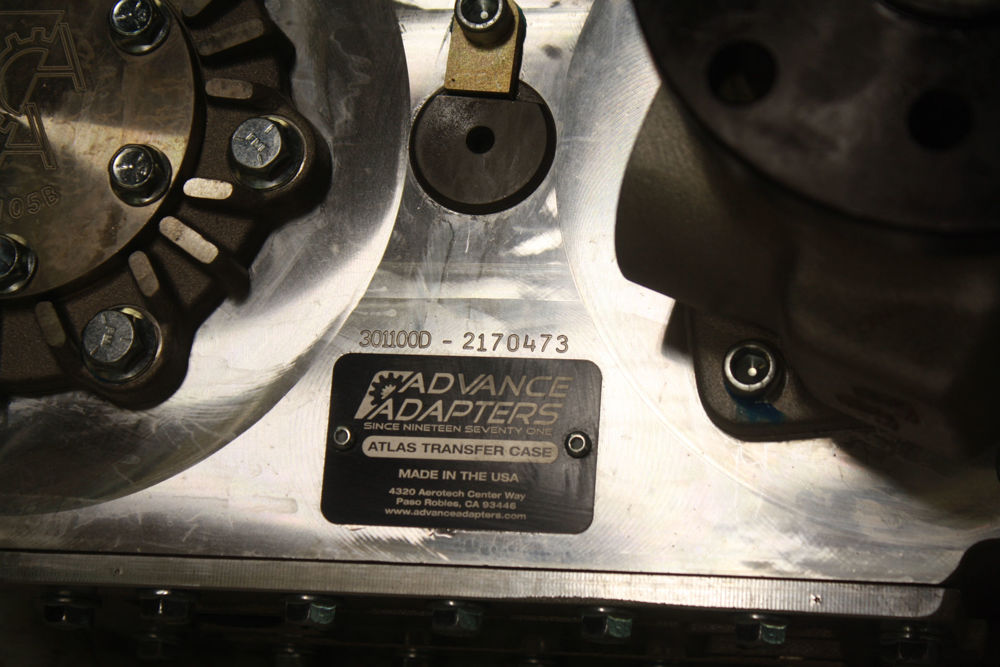
Transfer Case Identification:
All Atlas transfer cases come with an identification number that correlates to a customer order number. This number can be found on the back of the housing below the cluster pin or above the Atlas tag.
Lubrication Specifications:All Atlas II transfer cases are shipped dry.
All holes are plugged with red plastic caps to keep contaminates out during shipment.
Preferred lubricant:Red Line MTF GL-4 for most units, Red Line Heavy Shockproof for the races cases and Red Line ATF for the cases with our oil pump tailhousing or also known as the "FLAT TOW CASES". Other brands of oils can be used but should be a synthetic with a GL-4 rating.
Capacity: 2 speeds is 2.0 quarts and the 4 speeds are 2.5 quarts
The Atlas includes a site tube to help you determine the correct fluid level. Once the required quarts are installed, we recommend marking the oil level on the site tube. A small zip tie or hose clamp works well for this.
Operation Temperatures:
Normal Operating Temperature: 160F - 175F Degrees
Vehicles using high horsepower or pulling heavy loads 190F - 220F
Max Intermittent Temperature: 230F - 240F Degrees
Lubrication Notes: Too much fluid will cause foaming at high speeds. Foaming oil expands and fills the entire cavity, which forces fluid out the breather tube; or the breather hose may be restrictive, causing the Atlas to build up pressure.
Advance Adapters recommends a minimum of three feet of 3/8" fuel hose for proper ventilation. This hose should be connected to the brass elbow located on top of the Atlas.
Your warranty could be voided if the proper gear lubricants are not used and proper oil levels are not maintained.
Maintenance: Lubricant should be changed 500 miles (first time)
Atlas oil levels should be monitored frequently. After the oil is replaced from the first 500 miles. The oil should be changed at intervals of 10,000 to 15,000 miles thereafter.
Re-torque fasteners: Check bolt torque on yokes 1st time 10,000 miles, 2nd time18,000 miles
Warranty: 12 months from delivery of vehicle to customer, unlimited miles.
Checking oil: Check oil level on level ground.
Drain oil: Remove lower plug on oil pan or fitting on lower site tube.
Refill: Install drain plug. Fill lubrication through upper site tube on back side of Atlas.
General notes on Shifting: The Atlas Transfer Case is a Synchronized gear box. This means that in order for the case to shift easily and smoothly the vehicle must be moving in a forward direction. This will allow the synchronizers to function properly. Note that when the transfer case is shifted when not in motion, the clutch teeth may or may not be aligned. If the teeth are aligned, then the unit will slip into gear easily.
Towing: When a vehicle is being towed with the Atlas, the shift levers should be in the Neutral position.
Transmission towing positions are as follows (please also verify in your owner's manual what the vehicle manufacturer recommends):
Automatic transmissions should be left in park.
Manual transmissions should be left in any gear.
Troubleshooting-Noisy Operation:
Since the Atlas is gear driven, it will typically create more noise than a typical chain driven transfer case. This noise is more noticeable on applications where the direct lever type shifter is used.
Should your Atlas exhibit a new sound, check the oil level and inspect the color of the oil at the sight tube. If oil is low or appears to be contaminated, change it immediately.
Gear wine is typically a result of inadequate lubrication. This can result if a leak occurs or if water or other substance mixes with the lubrication.
If noisy condition is not remedied by oil change, disassembly and inspection of individual wear components is recommended.
Vibration: Vibrations can come from several areas in the drive train (transmission, drivelines, axles, tires). Such vibrations may be most noticeable at the Atlas shifter if equipped with a direct linkage type shift mechanism. Be sure to check other components prior to the Atlas. In most cases, vibration is the result of a worn component such as a CV driveline or failed transmission mount or isolator.
Improper driveline angles can also result in vibrations. Inspect both front and rear driveline angles in relation to the axle pinion yoke. Driveline angles greater than 4 degrees can cause a noticeable vibration. This type of vibration can be remedied by adjusting axle pinion angle.
Improper driveline angles are responsible for 99.9% of all noises that seem to be coming from the Atlas.
If all other components appear to be intact, check the Atlas front and rear output shafts for excessive movement. Improper yoke nut torque may allow a slight amount of in and out movement. Check the yoke nut torque specifications periodically. The 32 splined shafts should be torqued at 150 lb.-ft.
Difficulty Shifting:
There are two main reasons an Atlas may be difficult to shift. First, the linkage could be binding. You may need to inspect for possible trouble areas.
Notes on shifting:
Shifting the Atlas is an acquired touch and feel. You will not learn it overnight.
It is twice as hard to shift the transfer case if the vehicle is not at least slowly rolling forward. In addition, trying to shift the transfer case while the steering wheels are turned puts a bind on the synchronizers, making it almost impossible to shift in or out of gear.
Removal from Vehicle & Recommended Equipment:
- Floor jack to support the transmission when the crossmember is removed.
- Transmission jack for raising and lowering the transfer case.
- Pneumatic impact gun.
- Magnetic parts tray.
- Less debris/contamination in oil.
- More accurate part fitment.
- Maximizes oil seal life.
- Reduces bearing wear.
- Allows for easier assembly.
- Guarantees a good repair.
- Damaged used parts may indicate other problems.
Procedure:
1. Prior to removing the Atlas from a vehicle, place shifter(s) in neutral and drain the lubrication fluid.
2. Disconnect vehicle negative battery cable.
3. Remove front and rear drivelines from vehicle.
4. Disconnect shift linkage by removing e-clips that retain shift rod button ends.
5. Support the rear portion of the Atlas with a transmission jack or similar device.
6. Remove six mounting bolts that secure the transfer case to the transmission.
7. Disconnect the speedometer cable or wires.
8. Remove any wiring related to the 4WD/4L switches.
9. Remove the vent hose from the transfer case.
10. Separate the transfer case from the transmission by pulling straight back.
11. After separation, lower transfer case from vehicle.
Disassembly:Tools required: Dead blow hammer, ¾-inch socket, …ž-inch socket, ¼-inch Allen socket, ½-inch socket, assorted wrenches.
Procedure:
1. Start with a clean work area.
2. Remove the brass elbow on the top of the transfer case and any shifter componets.
3. Shift the unit into 4WD low range (both shift rods back into the case).
4. Set the unit upside-down on a work surface.
5. Remove all output yokes.
6. Remove oil pan and inspect internal components for signs of unusual wear.
7. Remove idler pin bolts and push the idler out of the case. remove the idler gear, careful not to drop the bearing out of this gear.
8. Remove the two thrust washers from the inside of the case.
9. Remove shift fork set screws.
10. Remove shift rail housing retaining bolts and tap the shift rails to remove this assembly out of the case.
Note: the shift forks will sometime bind during this step and they will require some adjusting to get the shift block off the case
11. Remove input housing bolts to free the input ring assembly from the transfer case.
12. Remove the 5 bolts (early units) or 8 bolts (newest) from the front output shaft retainer.
13. Remove 4 rear bearing cap bolts or 5 bolts on the "G2" case from the front output shaft.
14. Remove the front subassembly from the case.
15. Remove the five bolts retaining the rear output subassembly.
Cleaning and Inspection:
We recommend the following practices for powertrain assembly:
Part cleanliness:
Thoroughly clean all parts prior to assembly.
Part inspection:
Inspect used and new parts for signs of damage or wear prior to assembly.
- Magnetic drain plug inspection:
- Inspect debris collected by magnet.
- Easy to check when performing oil change.
- A small amount of material is normal due to wear.
- Larger amounts of debris may indicate a problem.
The Atlas transfer case consists of six subassemblies. Each subassembly requires a specific set of procedures. Six main sub-assemblies: (In order of assembly)
Other items needed for Atlas rebuild:
- Assembly lube for needle bearings and synchro ring.
- LocTite thread locking compound (medium strength)
- RTV silicone
- Synthetic grease
- Solvent
- Clean rags
TORQUE SPEC.
OIL PAN BOLTS, USE RTV SILICONE, 17 Ft-Lbs
INPUT HOUSING, USE MED. THREADLOCK, 30 Ft-Lbs
REAR OUTPUT, USE RTV SILICONE, 30 Ft-Lbs
FRONT OUTPUT HOUSING, USE RTV SILICONE, 30 Ft-Lbs
SHIFT RAIL HOUSING, USE RTV SILICONE, 30 Ft-Lbs
SHIFTER SUPPORT HOUSING, USE RTV SILICONE, 20 Ft-Lbs
REAR BRG. CAP HOUSING, USE RTV SILICONE, 20 Ft-Lbs
IDLER SHAFT, USE RTV SILICONE, 20 Ft.Lb
RETAINER - SPEEDO, USE RTV SILICONE,10 Ft-Lbs
SITE TUBE FITTING, USE RTV SILICONE, 15 Ft-Lbs
BREATHER FITTING90 DEGREE, USE RTV SILICONE,10 Ft-Lbs
PLUG - OIL PAN, USE SEAL WASHER, 10 Ft-Lbs
SHIFT SWITCH, USE SEAL WASHER, 12 Ft-Lbs
SHIFT FORK to SHIFT RAIL, USE MED. STRENGTH THREADLOCK,150 IN.Lbs
YOKE NUT- 32SPL , USE RTV SILICONE, 150 Ft-Lbs
ATLAS 4SP PLANET BOLTS, USE RTV SILICONE, 30 Ft-Lbs


